Introducing Pixinsight
- Welcome to Pixinsight
- Calibration and Stacking
- A Few Useful Tools and Tips
- Processing Linear Data
- Working With Colour
You have your shiny new copy of Pixinsight on your desktop, and a look of desperation on your face. Pixinsight does look daunting to the new user, but once you become familiar with it, it will be your go to astronomy software.
I will show you the basic methods from stacking your calibration frames, to calibrating your lights, and much more.
The methods I use to process astro images will only relate to SHO and RGB mono light frames, as I don’t have a one shot colour camera.
My workflow includes some paid processes, which greatly help in making the best possible end result for the data obtained. Any paid processes and links will be highlighted when I use them.
- Organising Folders
- Stacking Darks and Dark Flats
- Calibrating Flat Frames
- Stacking Flat Frames
- Calibrating Light Frames
- Blink
- Cosmetic Correction
- Register Lights
- NSG
- Summary
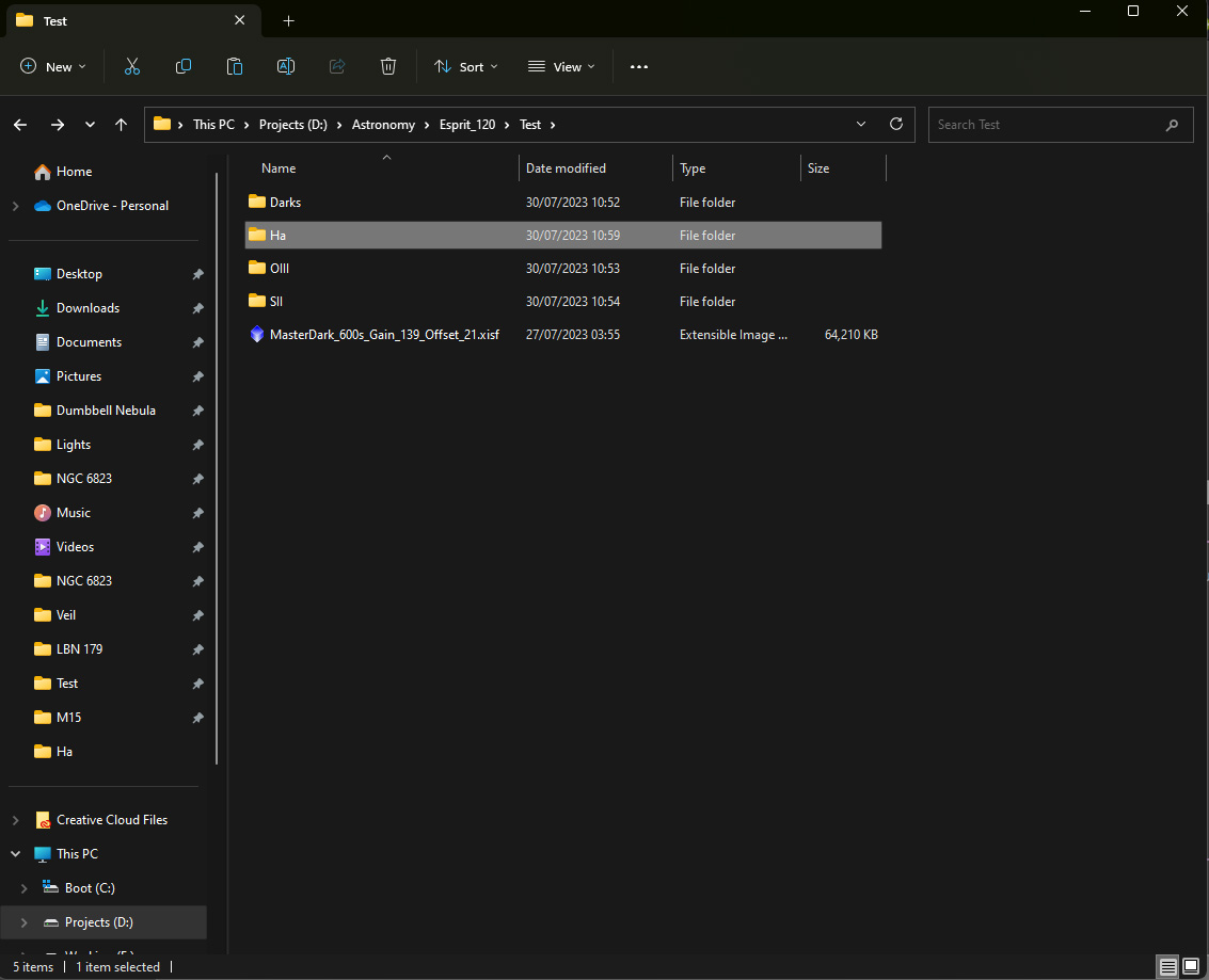
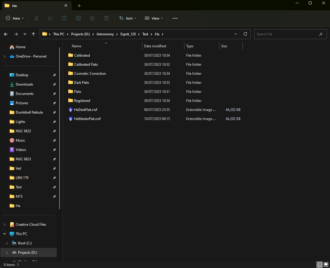
When executing the calibration process, a huge amount of files will be produced, so an organised folder structure is imperative, to avoid confusion. You may already have an existing folder structure you use, which will be fine. Here are a couple of screenshots of my folder structure, with the target name of test.
The first image is the general folder structure, for each filter used, plus the Master Dark frame. The second image, shows the folder structure inside the Ha folder, along with the Flat Dark and Master Flat for the relevant filter.
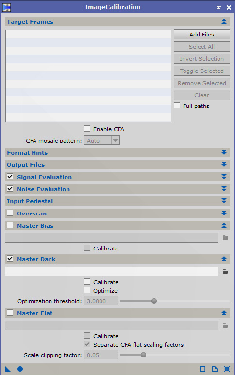
To stack any frames in Pixinsight, we use the ImageIntegration process, found under processes/all processes. The dark frames are loaded, and the settings below are used to stack the dark frames to make your master dark.
When you are ready to stack, click the blue dot indicated in the bottom image. The process will produce two rejection maps, and an integration frame. If you don’t want to generate the rejection maps, uncheck the box – Generate rejection maps. The integration frame is your master dark. Save it in the .xisf format and rename it to something more appropriate.
The exact same settings will be used to generate a Master Dark Flat, using your dark flat frames, which will be used to calibrate your flats. You will need a Dark Flat master for each of your mono filters.

![]()
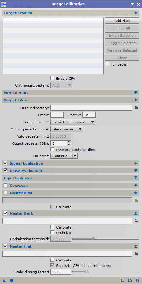
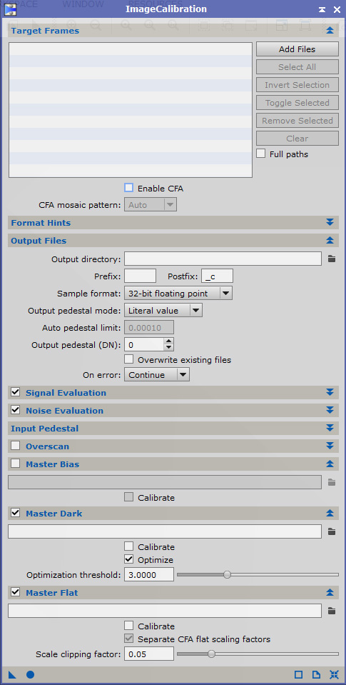
The next step in the calibration process, is to calibrate your flat frames.
First you will need to make a folder for your calibrated flats, where they can be accessed prior to stacking. This folder is loaded into the output directory box
As in the previous step, images below show the settings to calibrate your flats.
The Master Flat Dark for the relevant filter is loaded into the Master Dark box, not your Master Dark made in the first step. Make sure to uncheck the Master Flat box before calibrating.
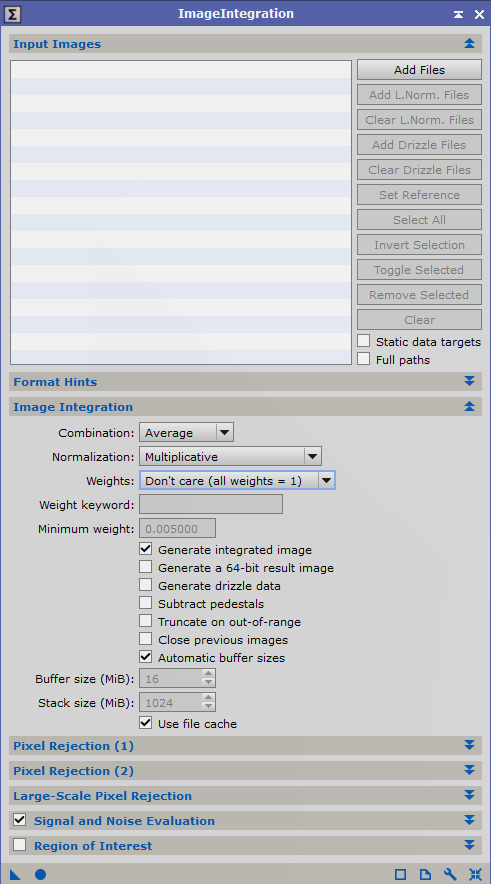
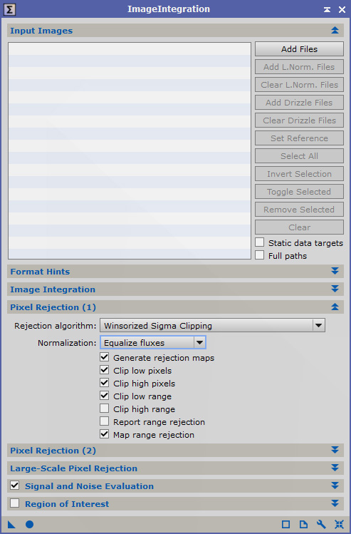
To stack our calibrated frames, we once again use the ImageIntegration process, but with different settings than when we stacked the dark frames.
As before, the Integration frame is our Master Flat, and needs to be renamed appropriately. This process will need to be repeated for each of your mono filters. Which means if you are making an SHO image, you will need a Master Flat frame for each filter.
Calibrating the Light frames with the Master Dark and Master Flat, is the final calibration step before the process of working on the light frames to finally stack them. We load our light frames collected from our imaging run, then we choose a folder to save our calibrated lights in. Then we insert the Master Dark and Master Flat in the appropriate boxes, and once again hit the blue dot. This process needs to be repeated for each filter, using the appropriate Master Flat for the light frames.
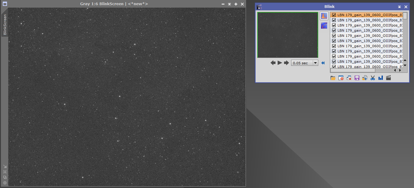
The first process applied to our calibrated light frames, is Blink. Blink allows you to inspect the light frames for bad defects such as plane trails, or elongated stars. The affected lights can be deleted from the folder, so as not to spoil the final stack.
You will find Blink, under Processes/All Processes. Load your Light frames into Blink, then press the button marked – apply automatic histogram.
My preferred method of inspecting the frames, is to zoom in to a 1:1 ratio, locate a good grouping of stars to look for any defects. Using the arrows, you can go through the frames one by one, or play the frames as a video. I prefer to inspect them one by one, if I come across a bad one, I can remove it, by using the button marked – Remove selected file to a new location. I have a folder called trash which I use for this purpose. Any affected files will be removed from the Calibrated Lights folder.
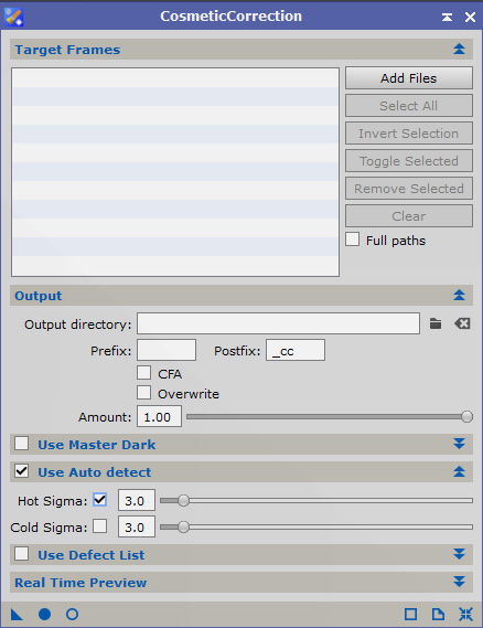
The next process on our lights, will be Cosmetic Correction. There are a couple of different ways to use this process, but I will concentrate on the simplest method. The image shows the loaded Calibrated Lights, and the settings I use. Files should be saved to the Cosmetic Correction folder for the relevant filter.
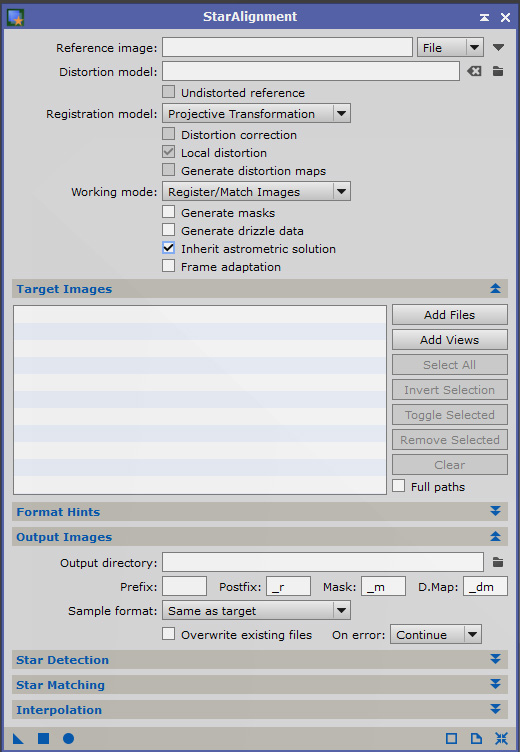
Once Cosmetic Correction has finished, we need to register our light frames, so they are all aligned with each other. For that purpose, we use the Star Alignment process.
With the first filter we will choose a frame from the CC folder as the reference frame. Once the calibration processes have resulted in a stacked image, we can use that stack as the reference frame for the remaining filters.
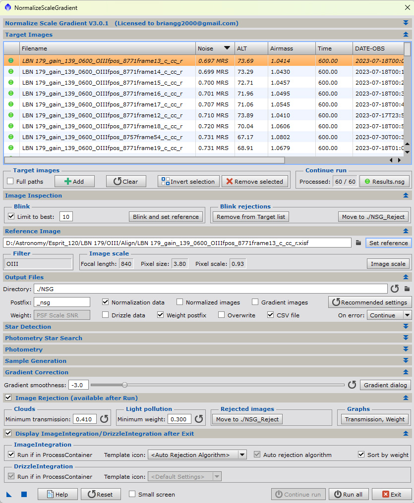
NSG stands for NormalizeScaleGradient. It is a script found under Scripts/Batch Processing. This script will normalize frames taken under different seeing conditions, or frames taken over different nights. It makes the later removal of gradients much easier.
Below are the settings I use, the top frame is usually the one with the least noise, and the one I use as the reference frame. Load the registered Lights for the relevant filter. Select the top frame, then click the button marked – Set Reference.
Click the – Run all button at the bottom, the script will work it’s way through the light frames. The script will make a folder called NSG in the Registered folder, which it will use to Normalize the Light frames during stacking.
Once the script has finished, click the exit button. This is where the magic happens. Once you have exited the script, it will open ImageIntegration with all the loaded files, and correct settings. All you need to do is press the blue button to stack the frames. The stack labelled Integration is your stack for that particular filter. If all goes well, you will repeat this for your other filters, and end up with 3 filter stacks. Don’t forget to label them, and save them.
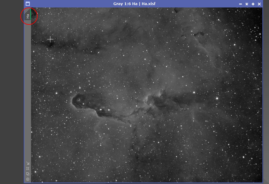
To label your stacks, right click where indicated by the red circle. Click on – Identifier, there you can rename your stack. This is not saving your stack, you will still need to save it in your target folder.
If all goes well, you will have 3 mono stack ready for further processing. Here is a brief summary of the workflow.
- Stack Dark frames
- Stack Dark Flat frames
- Calibrate Flat frames with the Master Dark Flat.
- Stack calibrated Flat frames.
- Calibrate Light frames with the Master Dark and Master Flat.
- Blink your frames
- Apply Cosmetic Correction to each set of filter frames.
- Register frames from Cosmetic Correction with the Star Alignment process.
- Apply NSG to each set of filters in the Registered folder.
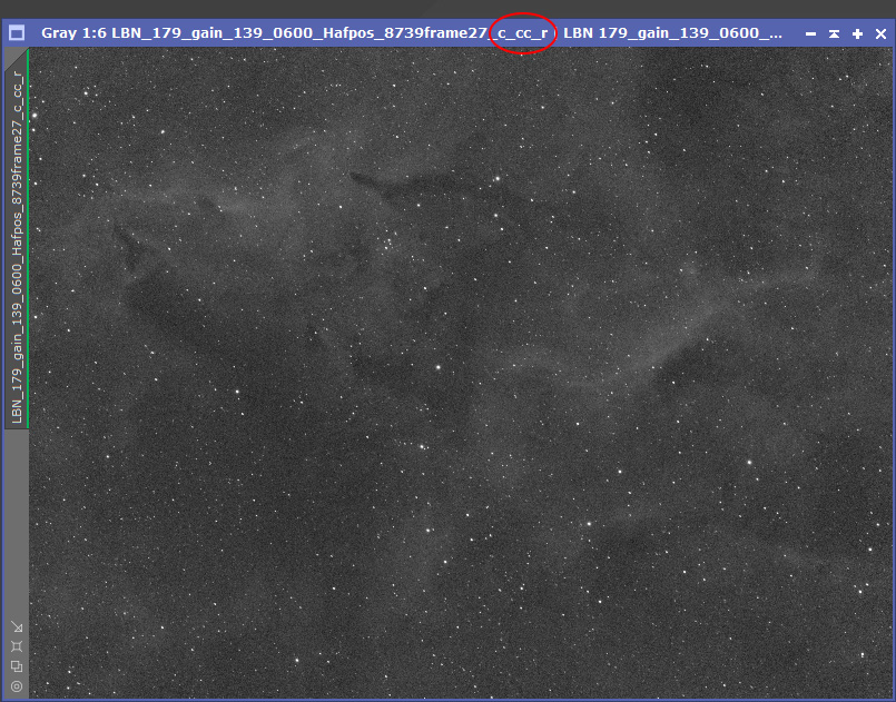
Before stacking, make sure your frames have the following in the title. c,cc,r. The c means the file is calibrated, cc means Cosmetic Correction has been applied, and r means the file is aligned. If one of those letters is missing, you missed out a process.
- ScreenTransferFunction
- Open Images
- Preview Mode
- Process Icons
Pixinsight has a myriad of tools to choose from, most are found either under processes, or scripts. Here are a few that you will use on a regular basis.
Probably the most used tool in the Linear state of an image, is the ScreenTransferFunction, or STF. This process allows for a temporary stretch to be applied to an image. It can also be used to refresh an linear image after a process has been applied to it. Another use for the STF is applying a final stretch in conjunction with the HistogramTransformation, but that comes later.
There are two ways to apply the STF, one is by opening the process, the other is by using a button in the task bar.
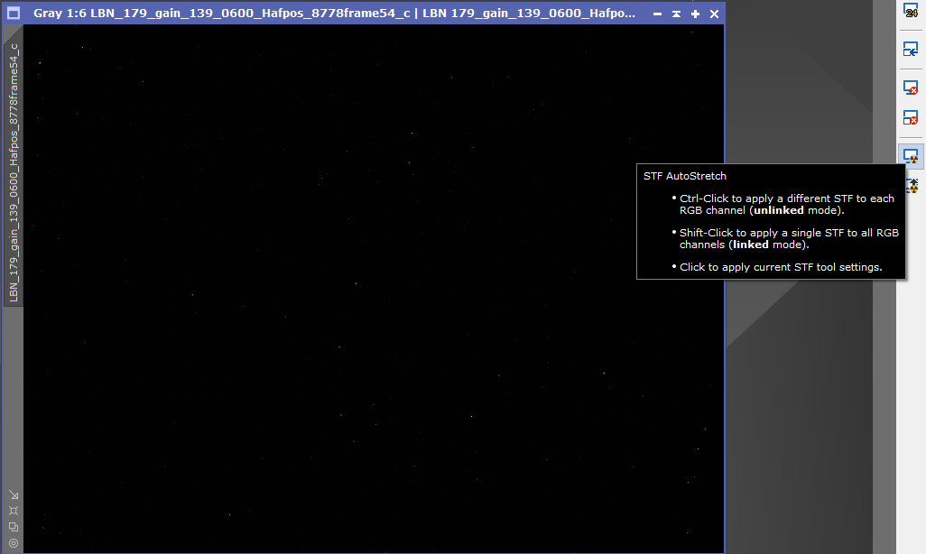
As you can see from the first image, the linear image is black, to apply a temporary stretch we press the nuke button, which is circled.
The second image shows the frame after the nuke button has been applied.
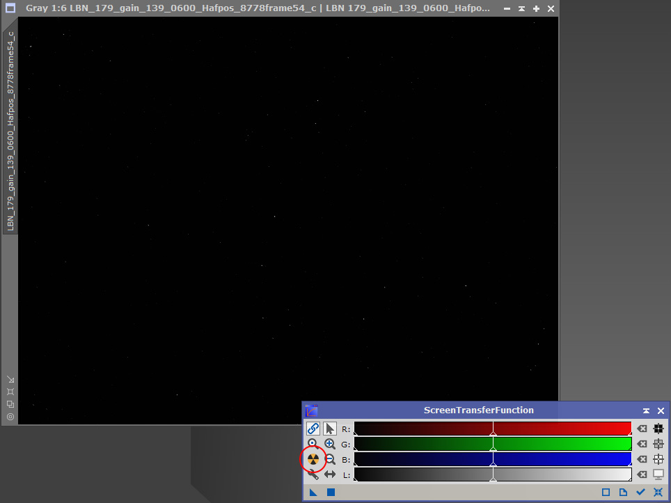
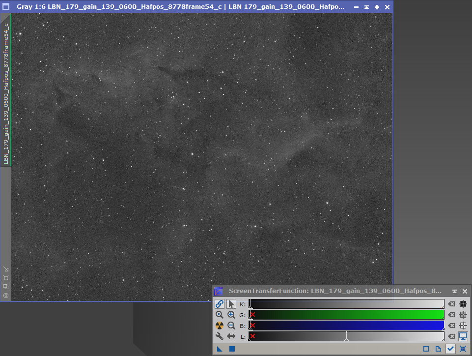
Above the nuke button, you can see a link button. This needs to be activated when used on a RGB stack, but de-activated on a SHO stack, to give a true representation.
In the second image, where the STF has been applied, you will see a vertical green stripe on the left edge. This green stripe denotes an image is still in the Linear state, and has not been permanently stretched.
The other way to use STF is by using the button in the task bar. This is also useful, because above it lies buttons to remove or reset the STF. Hovering over the buttons will reveal a tooltip, with instruction on what the tool does. This applies for most processes in Pixinsight.
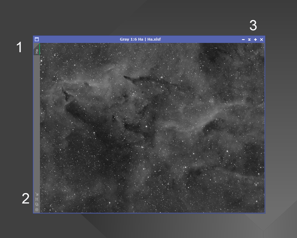
An open image in Pixinsight has a few buttons and tabs located in different positions, as seen by this example.
The tab marked No1, is the identifier tab, where you can rename the image by right clicking on it, then clicking identifier on the box that opens. This tab can also duplicate the image by clicking and dragging the tab. A clone of the image will be produced.
The buttons marked No2 are all connected to zoom levels. Hovering over these buttons will reveal tool tips showing the different zoom levels. The middle mouse wheel can also be used to zoom in and out. Holding down the spacebar allows for a zoomed image to be panned.
The buttons marked No3, can minimize or maximize the image, which is useful when you have a lot of open images on the workspace.
One other tip with open images is the ability to check if they are aligned correctly. Drag one image over another until they snap into place. By clicking the title bar of the top image, it will become semi-transparent, allowing you to see the underlying image.
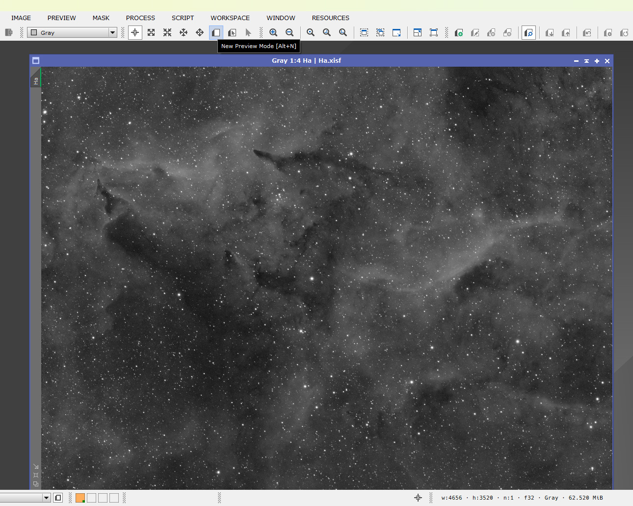
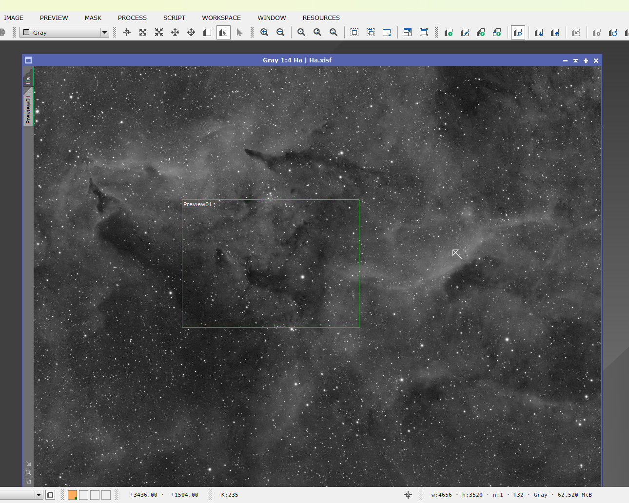
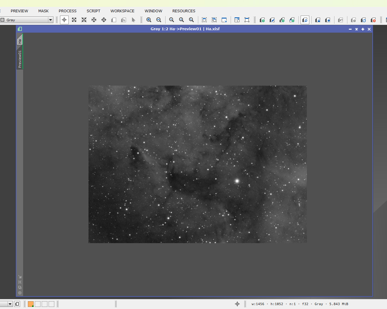
A very useful tool when processing is the preview mode. To activate the preview mode, click on the button highlighted in the top image. Once activated, a preview can be drawn on the image with the mouse, as shown in the second image.
Once a preview has been drawn, it is accessed with the preview tab on the left of the image. The preview is shown in the 3rd image.
The advantage of a preview, is it allows you to apply a process to the preview, without committing it to the actual image. This allows for settings to be changed and previewed before applying them permanently.
Deleting a preview can be done either through the preview menu, or by right clicking on it, and deleting it.
One of the most useful features in Pixinsight, is the ability to create icon sets. An icon set, is a collection of your most used processes condensed into an process icon file, which can be loaded into Pixinsight and save a lot of time searching through the hundreds of processes, for the one you need.
Creating your icon set in order of your workflow will save even more time. Begin by opening one of your processes, in the first image you see I have opened ImageIntegration. To make the icon, drag a new instance of the process, by clicking the blue triangle and dragging.
The next step is to close the ImageIntegration, right click on the icon, click – Set Icon Identifier, rename it to ImageIntegration.
Drag this icon over to the right hand side of your workspace. Repeat this process with all the icons you want in the set.
You will have something resembling the 3rd image. Select all the icons by left clicking and dragging over them, they will turn blue when selected (image 4). Right click on the workspace, select Process Icons/Save Process Icons. Save the set with a name you will remember.
To open your set of icons when you start Pixinsight. Right click on the workspace, select Load Process icons, find your icon set and it will load into Pixinsight in the order you saved it.
![]()
![]()
![]()
![]()
![]()
- Dynamic Crop
- ABE
- DBE
The first process immediately after saving your stacks is to crop them to remove any stacking artifacts. Using DynamicCrop will ensure the stacks remain aligned to each other. To perform this task we use a process called DynamicCrop, which is found in – Processes/All Processes.
Dynamic crop ensures all your stacks will align with each other after cropping. Cropping is needed to remove stacking artifacts such as image rotation, and effects from dithering. If these are not removed they will affect future processes.
To open DynamicCrop an image must be active. Once DynamicCrop is opened, the active image will turn paler and will be surrounded with a grey border.
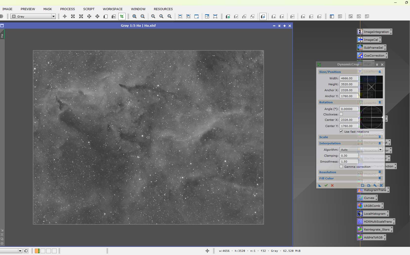
Hovering over one of the edges on this border will see the cursor change shape. The edge of the crop can now be moved to a desired position. Repeat for the other 3 edges until all artifacts are outside of the crop area.
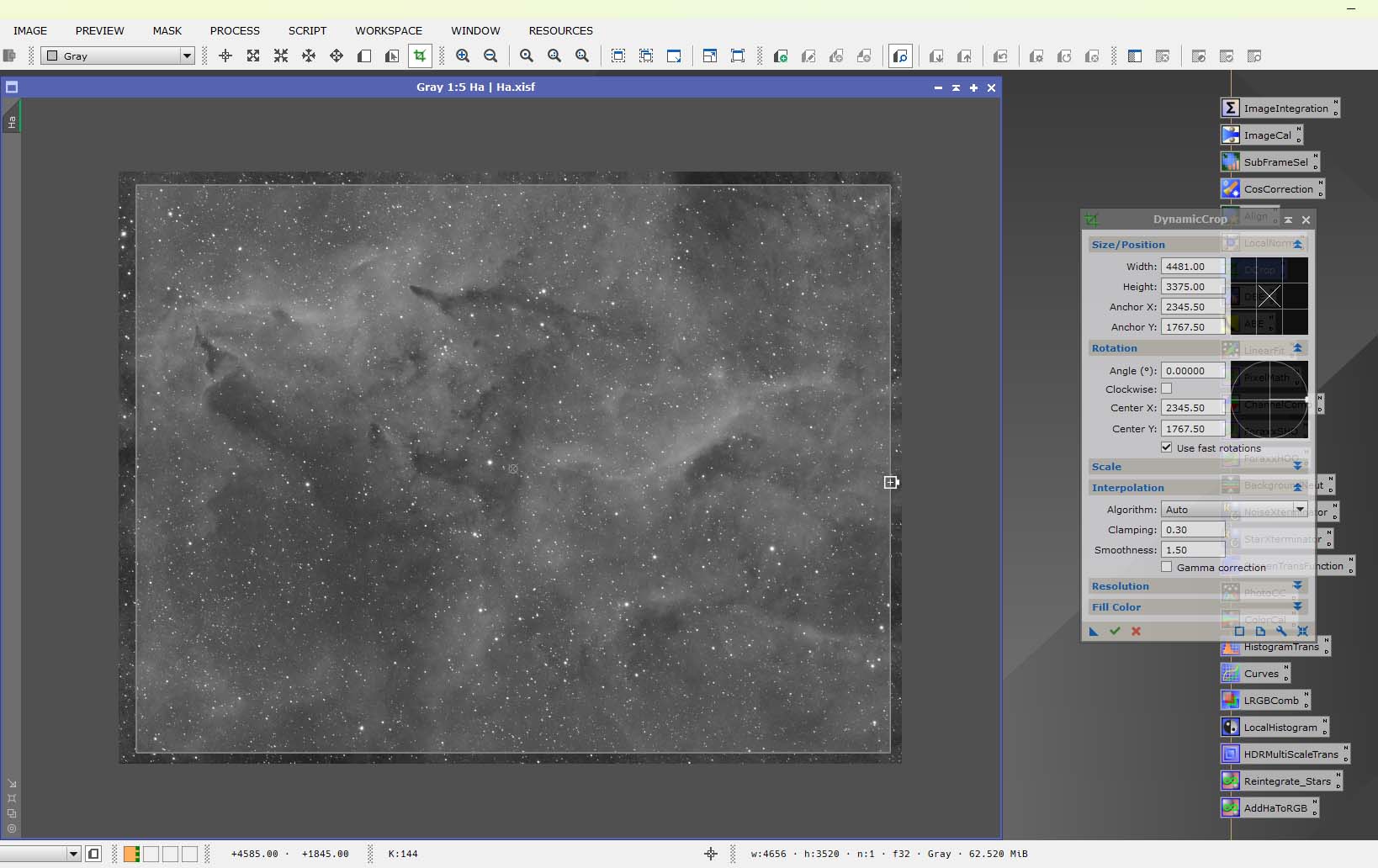
The crop can also be rotated by moving the cursor to a corner of the selection.
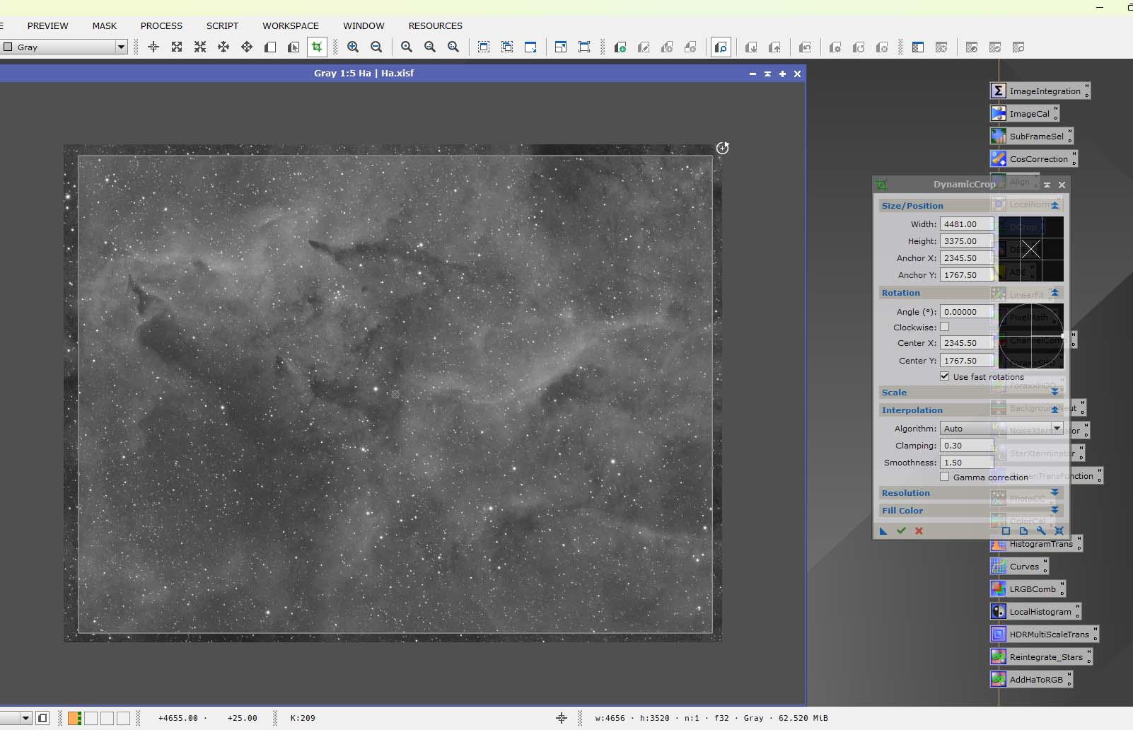
Clicking in the centre of the selection will allow for the whole crop area to be moved.
When you are happy with your crop, drag an instance from the DynamicCrop process using the blue triangle bottom left of the DynamicCrop. This is very important, as this new instance will contain all the information from the process.
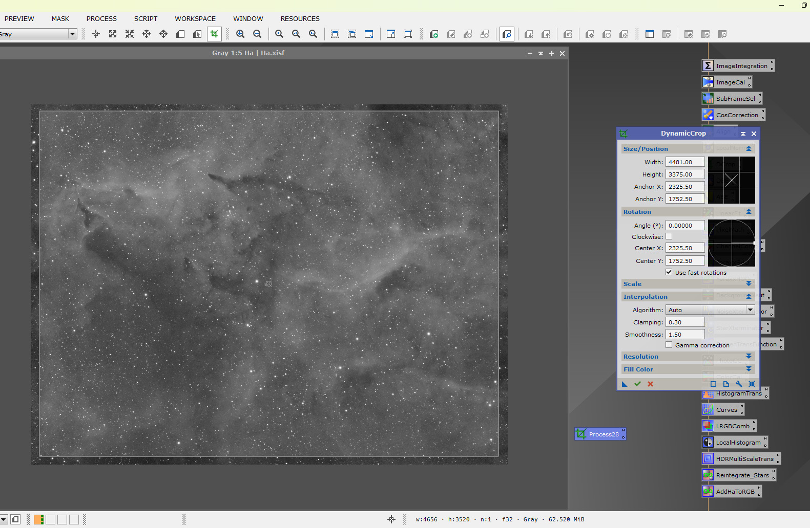
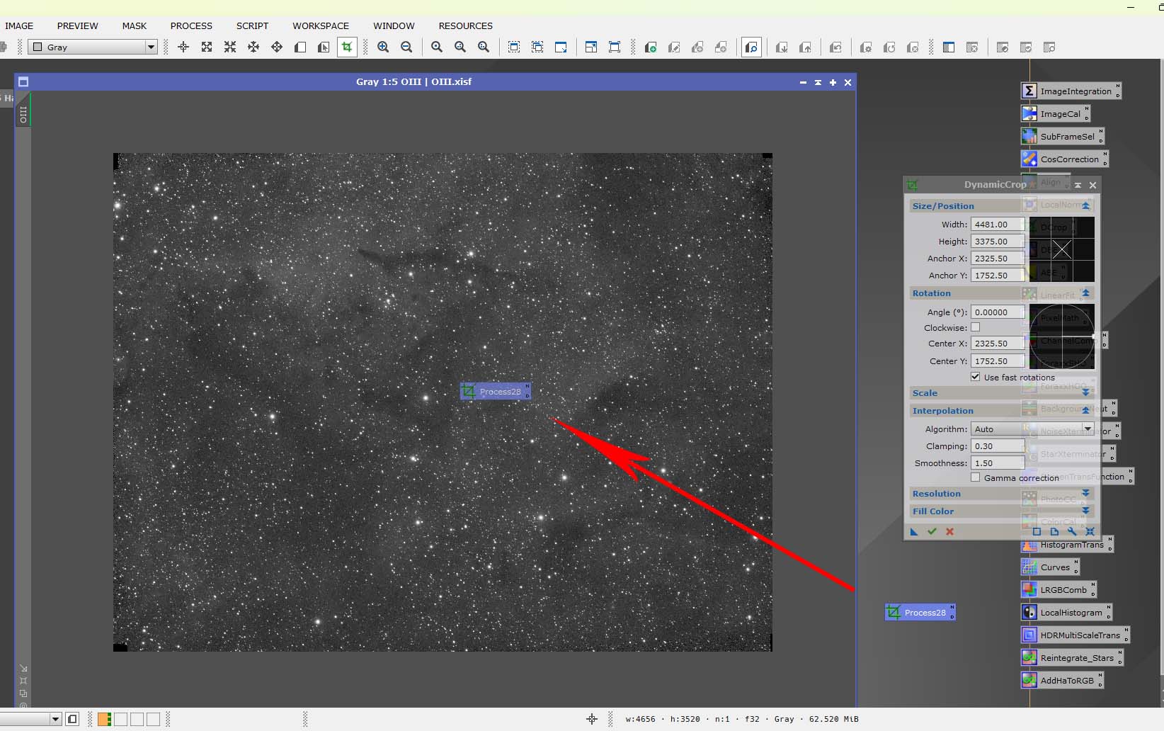
To execute the DynamicCrop process, click the green tick located bottom left of the DynamicCrop. To crop the remaing stacks, drag the instance over the open stacks, this will crop the stacks exactly to the same dimensions as the first crop.
ABE is the acronym widely used for the AutomaticBackgroundExtractor process in Pixinsight.
As the name suggests, this process automatically removes background gradients from an image. It is considered inferior to DBE, which will be shown later.
ABE is recommended for images with full frame nebula with little background, as DBE needs the background showing to work effectively.
Below are the settings I use as default. The only change I might make is in the correction method. For a normal gradient, the subtraction correction method is used. For an image with vignetting, the division correction is preferable.
The – Discard Background Model and Replace Target Image boxes can be checked if desired. I prefer to leave them unchecked.
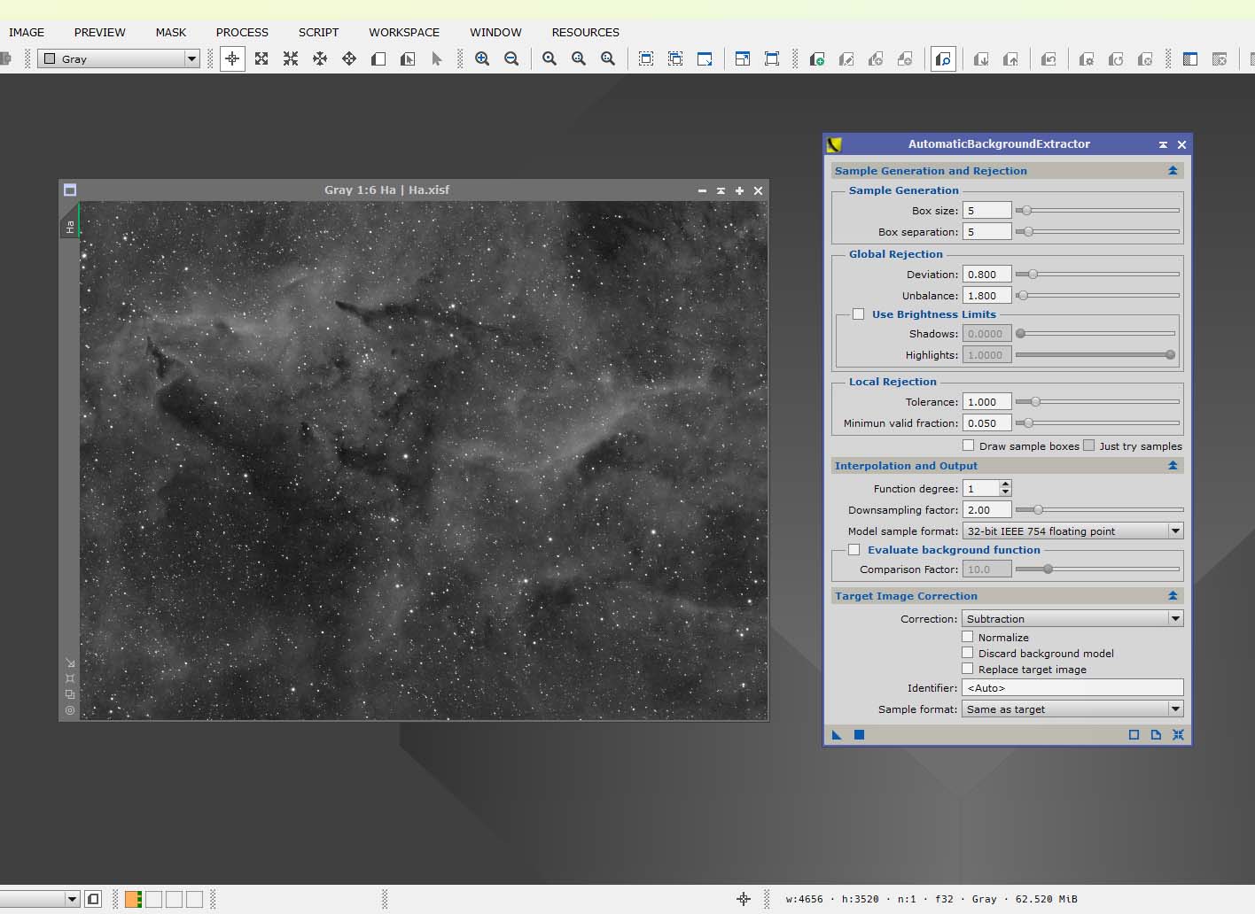
To correct the image, drag the blue triangle over each of your stacks.
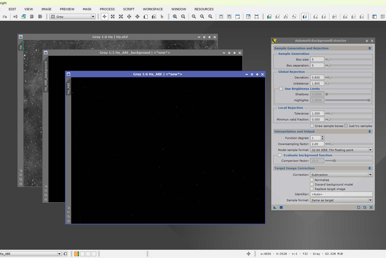
The corrected image will produce 2 files, the ABE frame and an ABE Background frame. Apply STF to the 2 frames, this will show the corrected frame, with the background removed, and the gradient that was removed. Save the ABE frame, the ABE Background can be deleted.
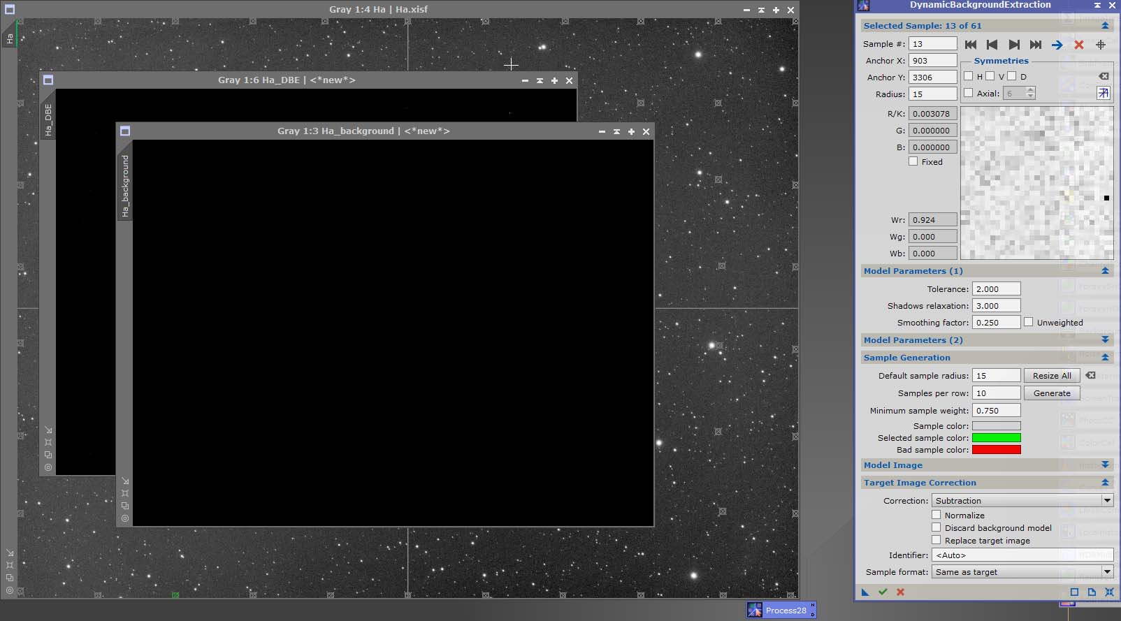
DBE is the acronym for the DynamicBackgroundExtraction process. It is similar to the ABE process, but the user has more control over the input. An image has to be active for the process too open. A crosshair appears on the target image once DBE is activated.
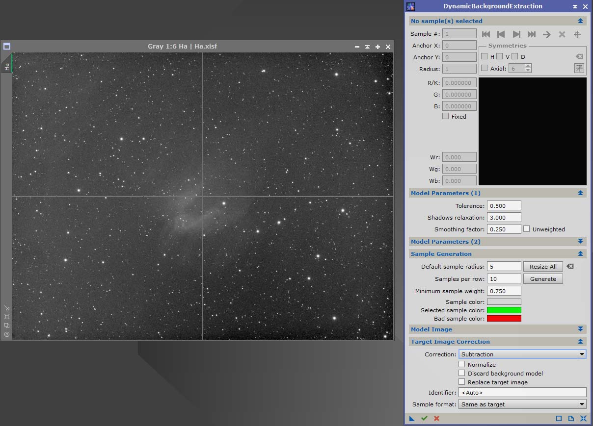
DBE works by placing square samples over the open image, either manually, or by letting DBE generate them automatically. As you see from the next image. I set a tolerance of 2 (blue Arrow), and a sample radius of 15 (red arrow). If your target is in a dense star field, the sample radius can be lowered to 5. If your target is a galaxy in a sparsely populated star field, the sample radius can be increased.
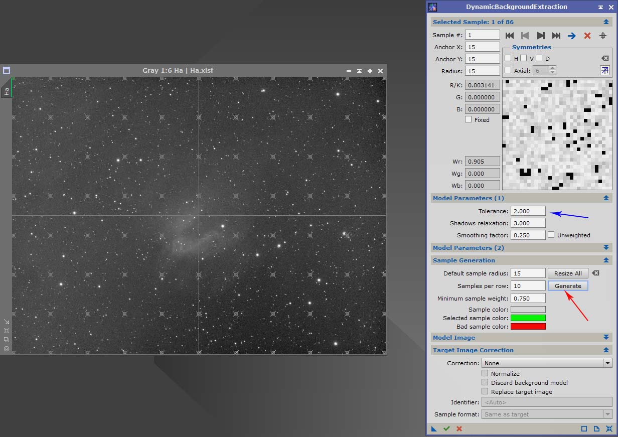
When the generate button is pressed the target is covered in small squares, but we can’t leave it this way. Any squares covering stars, or bright nebula will degrade the image, squares need to cover background only.
Zooming in to 1:1 ratio will make the job of deleting, or moving samples much easier. In the next image you can see a square that has a star in it, so it needs moving.
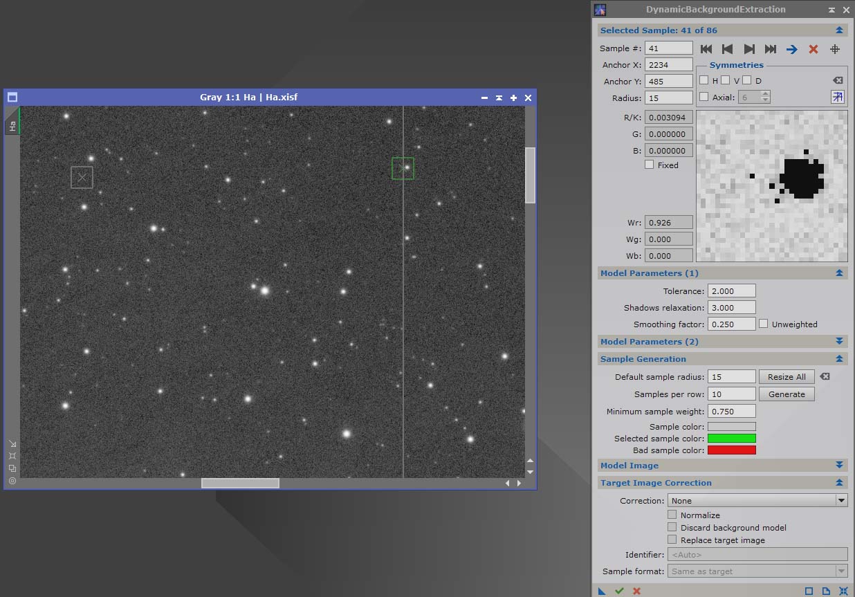
A square is moved by clicking on it, and dragging it away from a star or any bright nebula. To delete a square, click on it, then press the delete button.
When you are happy your squares are in the correct place, change the correction, to Subtraction.
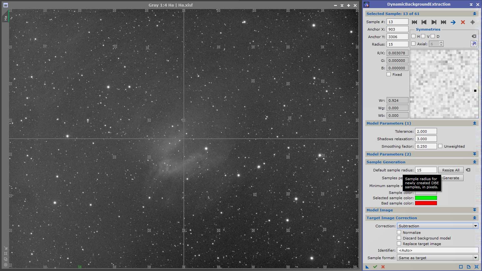
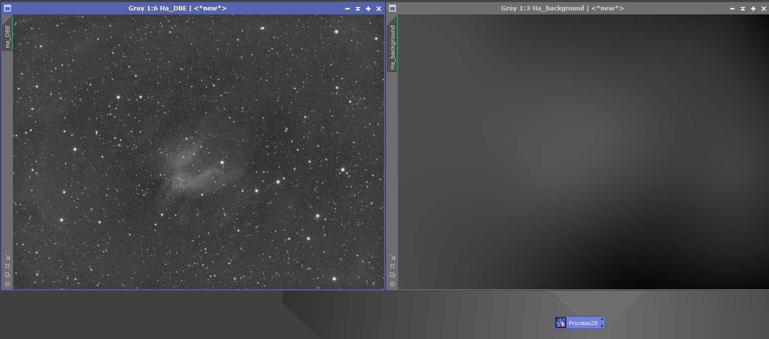
Clicking the green tick will activate the DBE process. The result will contain 2 files. A DBE file and a background file. The background is the gradient removed by DBE. The DBE file, is your corrected file. Before closing DBE, be sure to make an instance containing all the settings from your active process. This is done by dragging the blue triangle on the bottom left of the process. This instance can be used on the other filter stacks, making sure the samples are all in the same position.
Once you have your instance, DBE can be closed. Double clicking the instance, will apply the same settings to the other stacks in your image.
Using the STF process on the 2 images resulting from the DBE process will show the gradient removed, and the corrected target image.
- Channel Combination
- Colour Calibration
- XTerminator Tools
- Stretching
- Adjusting Colour
- Reintegrating Stars
There are many ways to combine SHO or RGB mono data in Pixinsight. Here we will combine the images with the simplest possible method. This method uses the ChannelCombination process, found in Processes/All Processes. Once opened, you will see 3 boxes in the process, all of which are set to auto.
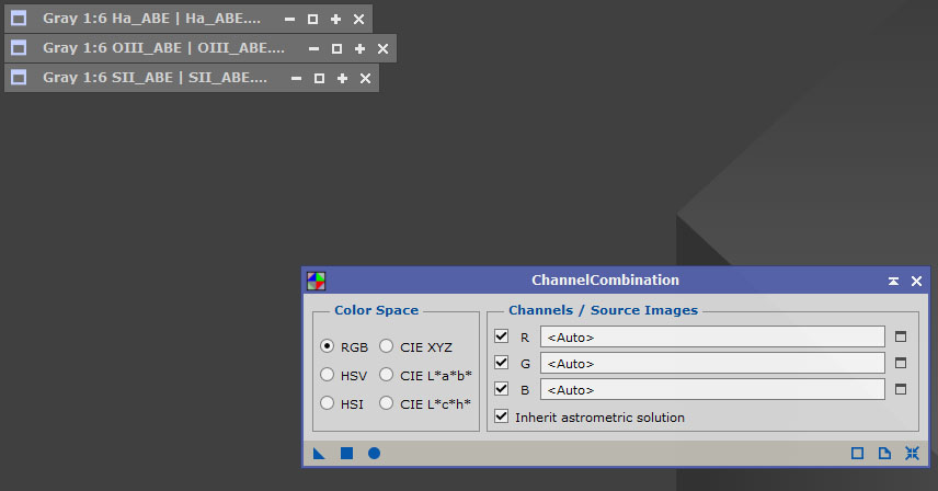
We don’t leave the boxes set to auto, Pixinsight will make a mess of the combination. If your data is Mono RGB, the Red frame is inserted into the R channel by selecting it from the dropdown box. The green and blue are selected the same way. Here we are dealing with an SHO combination, so the SII goes into the red box, the Ha into the green box and the OIII into the blue box.
Press the blue button – apply global, to combine the images. The result will be a combination named Image, followed by a number. I would rename it to something more suitable like SHO.
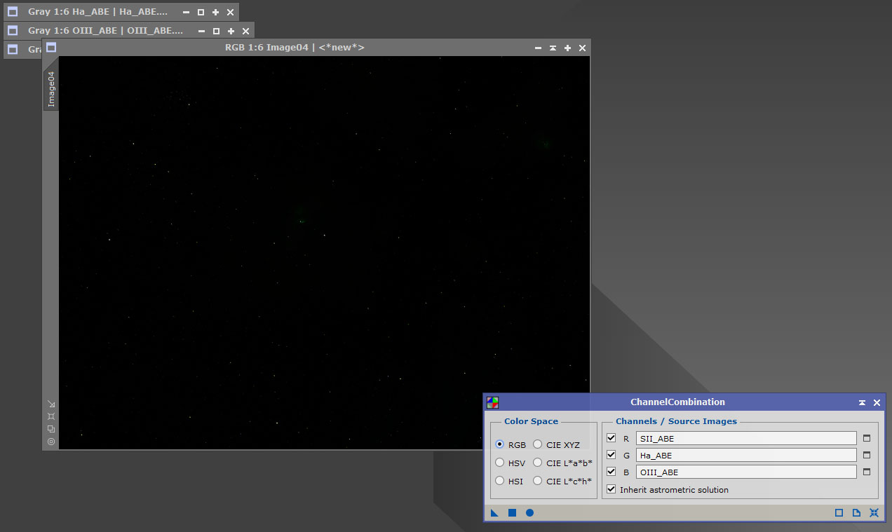
Applying STF to the combination will probably leave you underwhelmed, with the usual green and magenta that results from using ChannelCombination. This is not a problem and will be rectified in upcoming episodes.
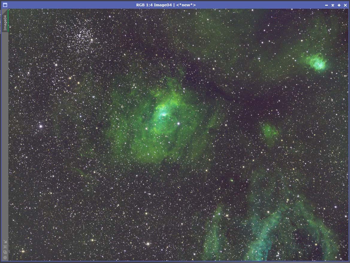
To colour calibrate the image, we will use a combination of ImageSolver and PhotometricColorCalibration. First we open ImageSolver, which can be found under Script/Image Analysis.
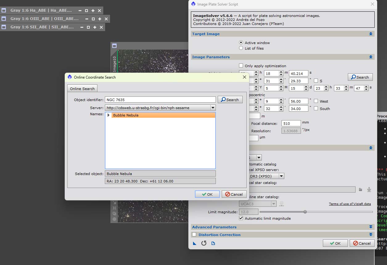
ImageSolver will fill in the details from the data in the image header, but to make sure, click search, enter the name of your object in the object identifier, click search again, then select the result from the search. Click OK, then OK again and let the ImageSolver work it’s magic. Once the script has solved the image, we can go on to the next step.
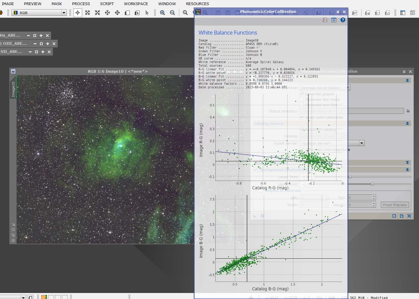
Open the PhotometricColorCalibration process, found under Processes/All Processes. Drag the blue triangle of the process onto the image, the result will be a graph, which you can discard, and your calibrated image, refresh the STF to see the changes made. The changes could be significant, or hardly noticeable.
For anyone getting into serious astrophotography, I would urge them to purchase the Xterminator tools. Yes they are another expense on top of the purchase price of Pixinsight, but they will make life much easier and improve your images tremendously. All the XTerminator processes can be downloaded as trial versions, so no immediate purchase is necessary. The 3 I would download, are StarXTerminator, BlurXTerminator and NoiseXterminator. These are the ones I will be using in this guide to Pixinsight. All the products can be found here.
All these Xterminator processes are applied to an image still in the linear state.
The first of the Xterminator tools we will use, is the BlurXterminator, which is a deconvolution tool, it will reduce stars, star haloes, and even drag out a little detail from the nebula, or galaxy you are processing.
Open BlurXterminator, leave at the default settings, they usually do a great job without the need to adjust anything. Make a preview on the image, select the preview, then apply the process by dragging the blue triangle over the preview.
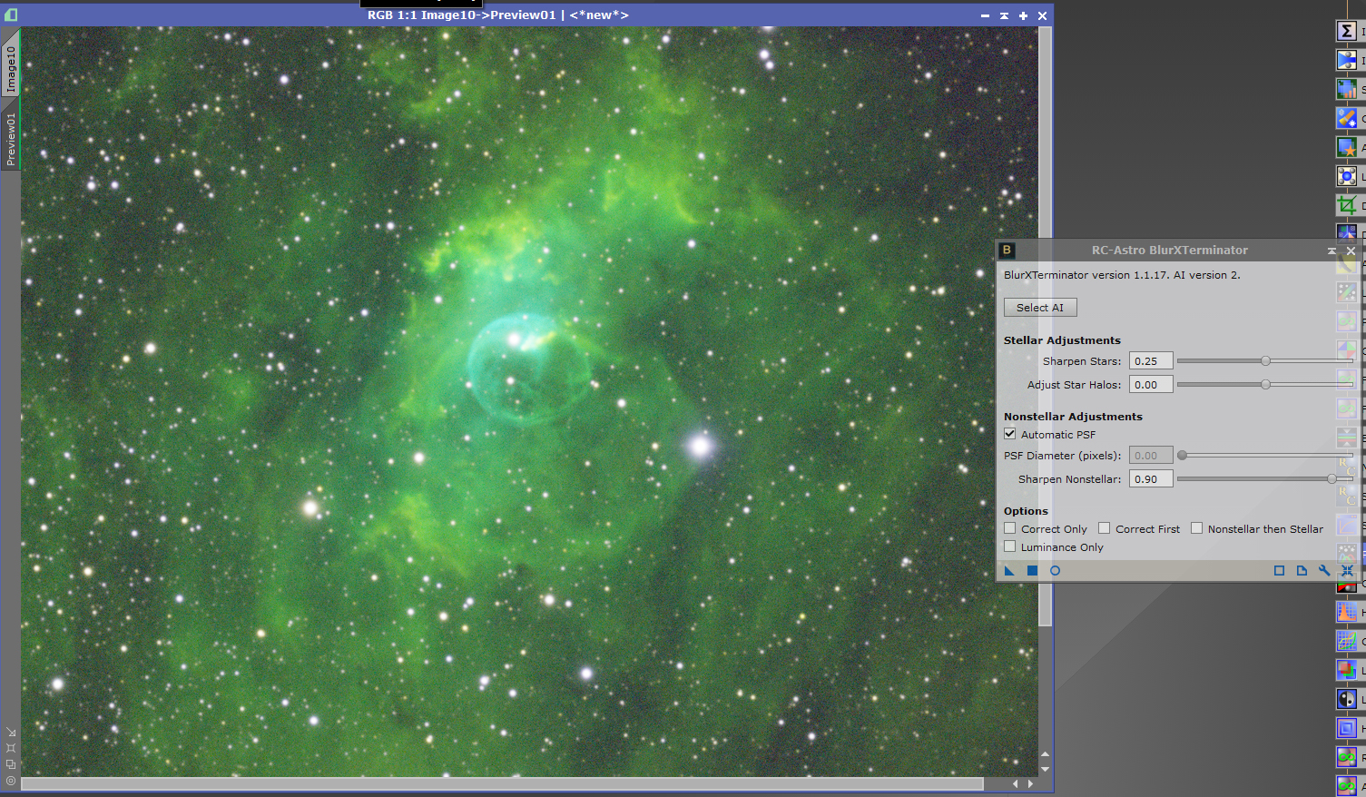
You will notice the difference in the preview once the process is applied to it. For a before and after view, click the icon which is highlighted on the taskbar.
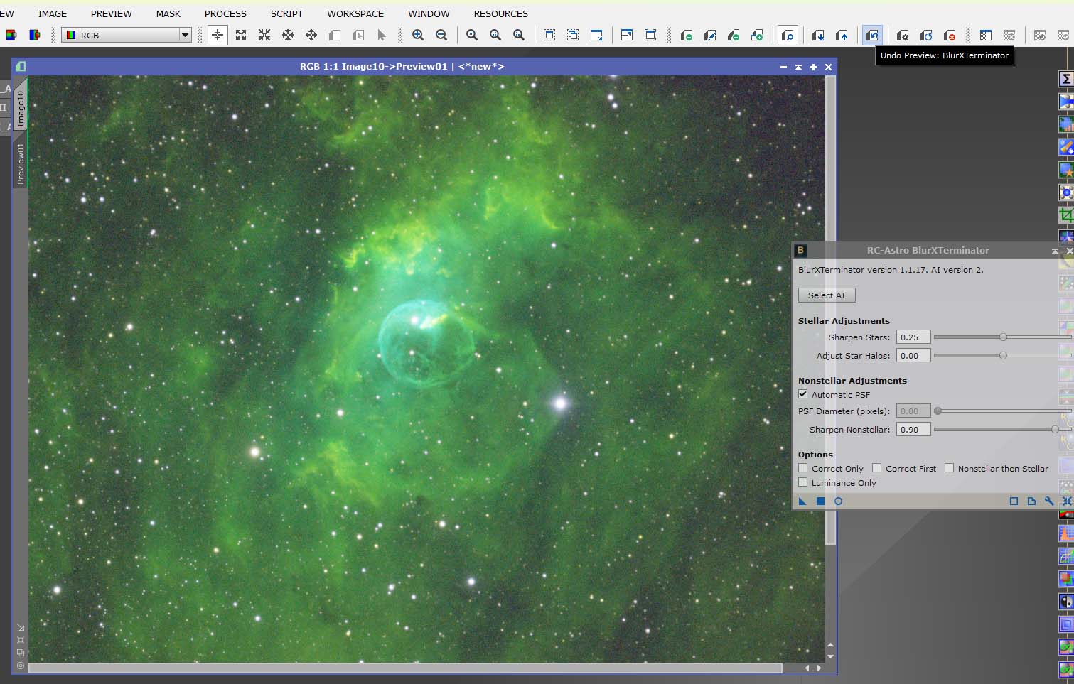
If you are happy with the result, select the image tab and apply the BlurXterminator by dragging the blue triangle onto the image.
Next process is the NoiseXterminator. As before, make a preview on the image and select it. Apply the NoiseXterminator to the preview, if you are happy, select the image tab, and apply the process. Use the default settings for now.
Below you will see before and after images of the results from NoiseXterminator.
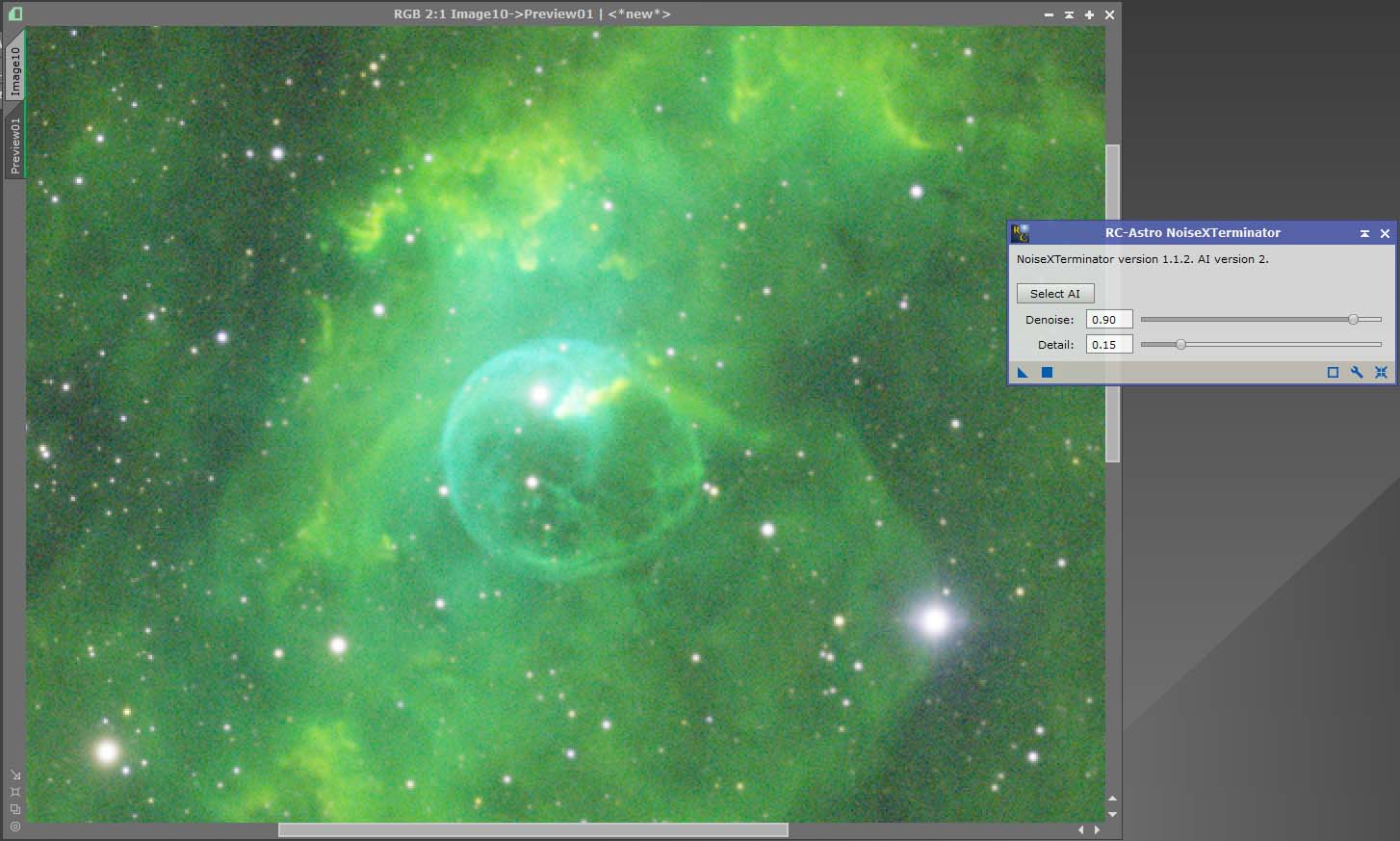
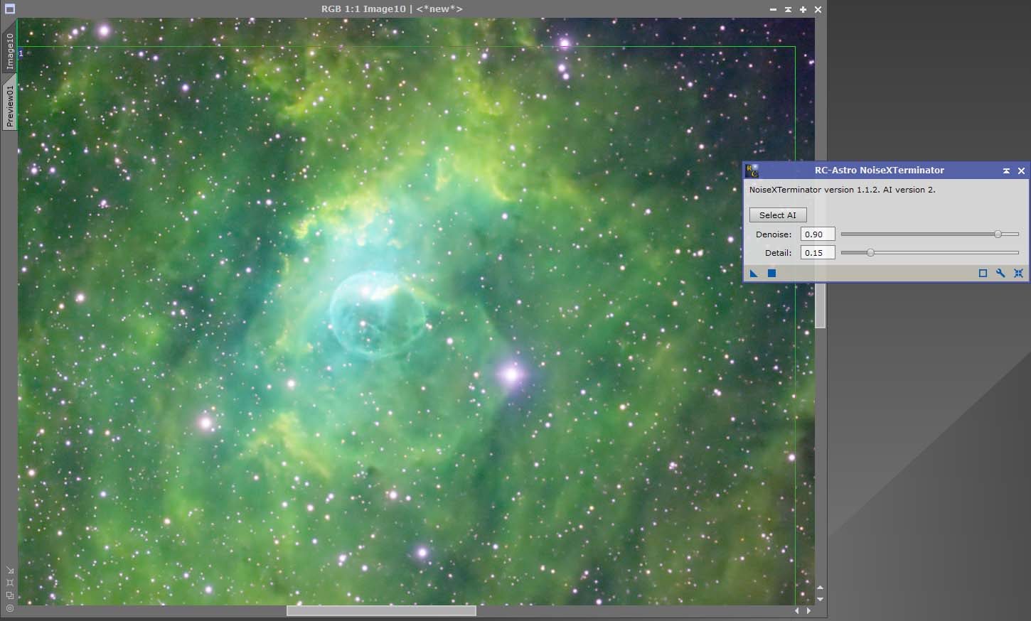
The final, and probably the easiest XTerminator process to use, is the StarXterminator. This process will remove the stars to a seperate image file, leaving a starless image file to stretch.
Although the StarXterminator tool can be used on non-linear images. I prefer to use it on linear images. It removes the risk of blown stars. Check the Unscreen Stars box if working on a non-linear image.
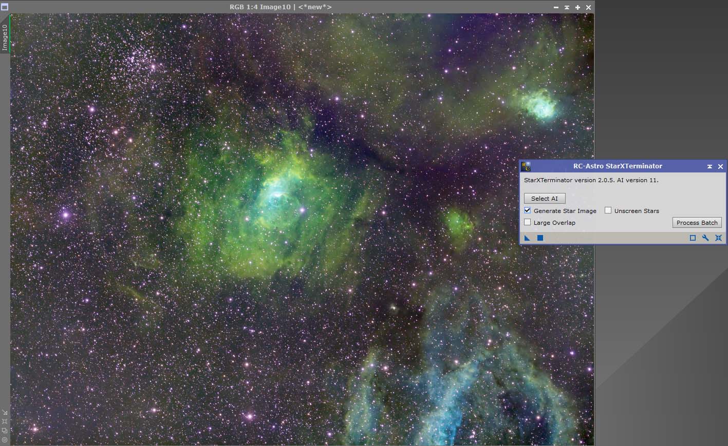
Apply the process in the usual way, by dragging the blue triangle over the image. The result will be 2 images, a star image, and a starless image.
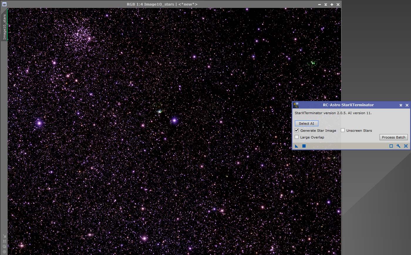
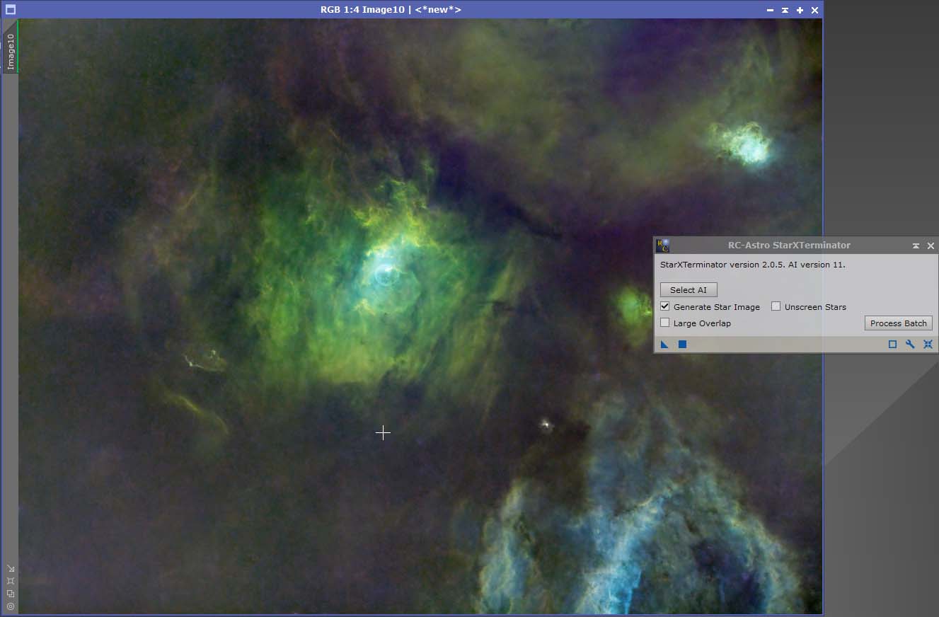
The final process of the linear data is to stretch the image into a non-linear form. There are many ways to stretch data in Pixinsight, but we will concentrate on the simplest method.
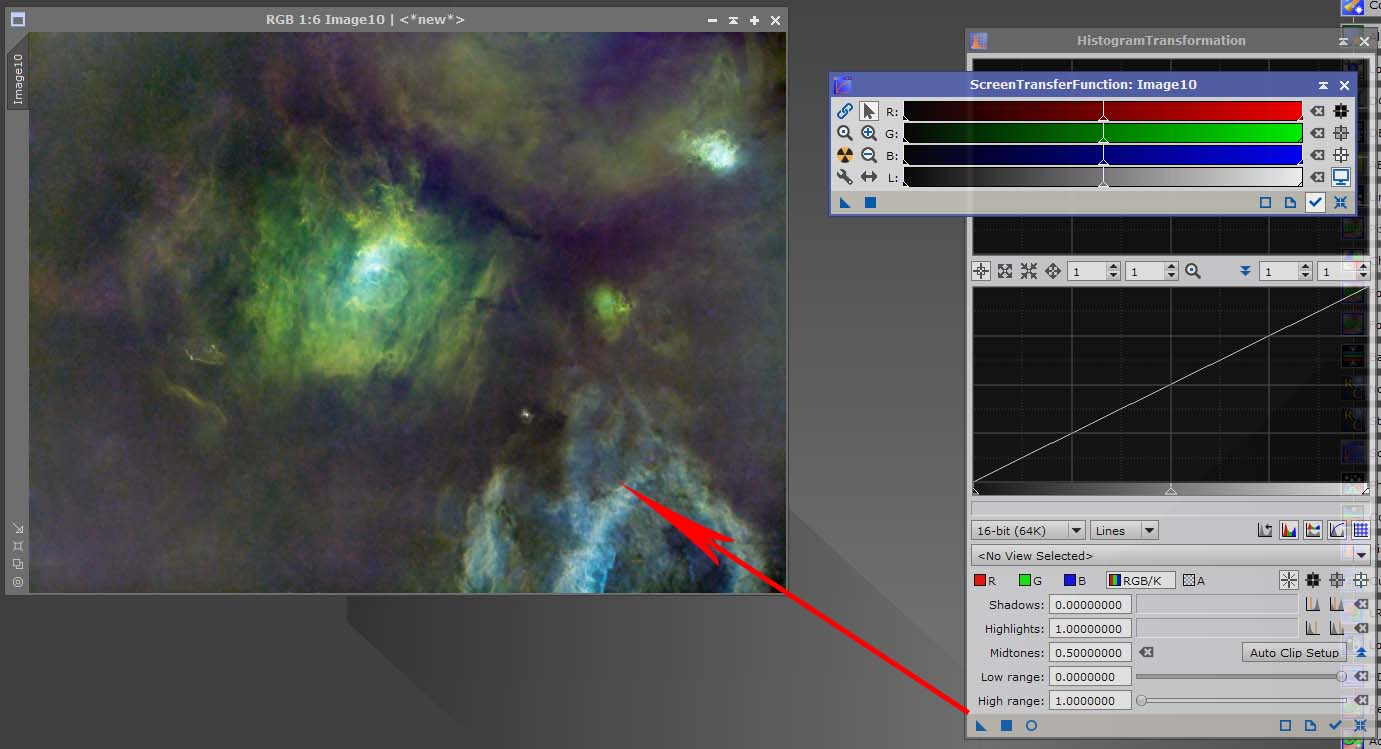
Open STF and the Histogram Transformation processes. Click the nuke button on STF, now drag the blue triangle on the STF, down to the Histogram Transformation, as shown in the image. When the cursor changes into a double triangle, release the mouse button. This will apply the settings from the STF onto the Histogram Transformation.
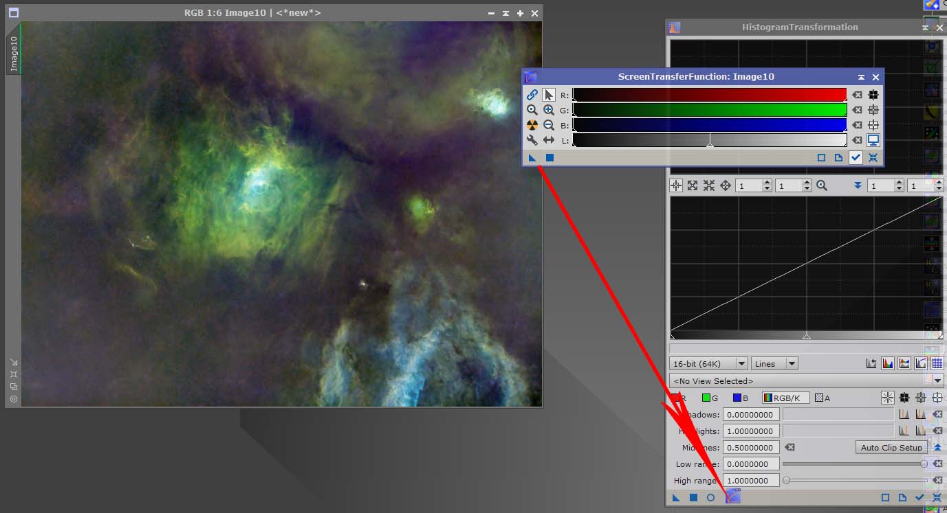
Remove the STF from the image by clicking the button highlighted in the next image. The image will turn black.
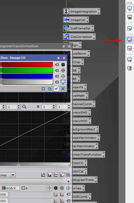
The finalise the stretching, drag the blue triangle on the Histogram Transformation process, onto the image. The image will be stretched, and the green line on the left hand side of the image will have disappeared.
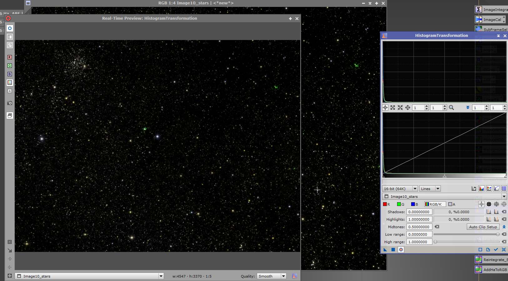
We will use a different method to stretch the stars, this will involve just using the Histogram Transformation process.
Open Histogram Transformation, select your image from the dropdown box. Remove the STF from the image.
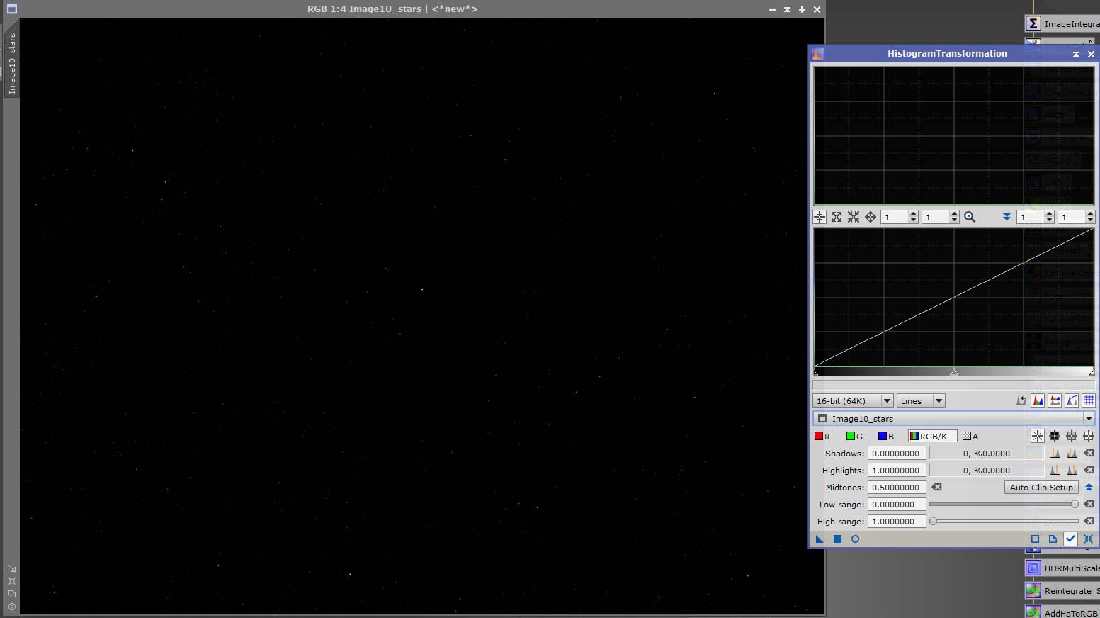
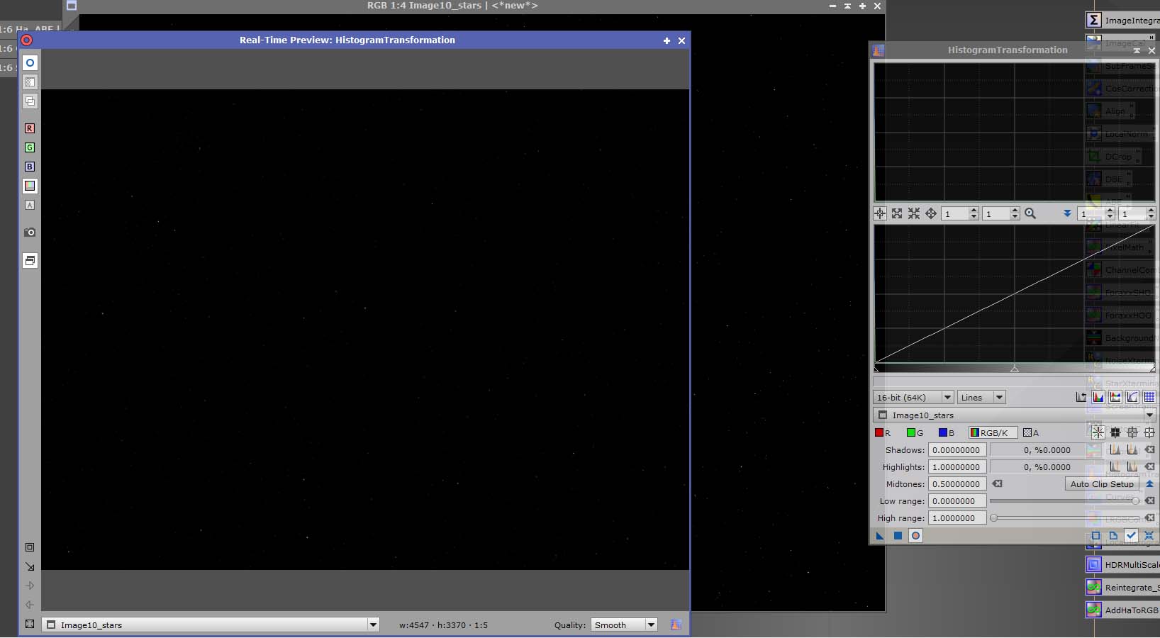
Open a real time preview by clicking the small blue circle on the Histogram Transformation. This allows us to monitor the stretching before committing the stretch.
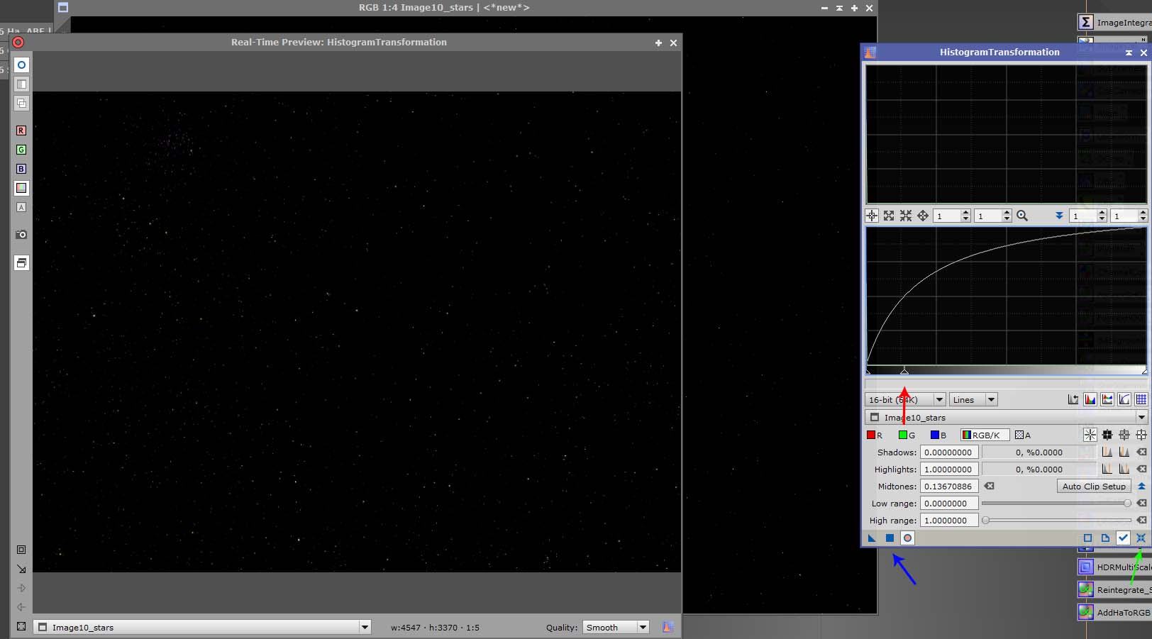
To stretch the image, we do it in stages, that way we have more control over the stretching. To begin stretching, drag the middle slider to the left of the histogram (red arrow). You will begin to see stars appearing in the live preview. To apply the stretch, click the blue square (blue arrow). Next, reset the histogram using the reset button (green arrow). Repeat this process until you are happy with the result. Less stretching means fewer stars that will not be blown out.
The final result should look something like this.
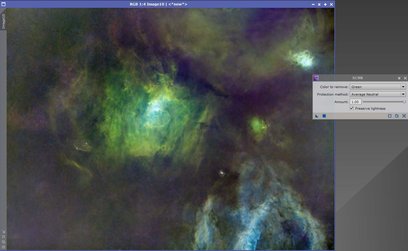
As you can see from out image, the colour is not great. The green and magenta need removing from the image. There are many ways to do this, but we will keep it simple. Open the SCNR process, found in Processes/All Processes. Applying SCNR will remove any green from the image. Experiment with the % used, to just remove all the green. Here I used 75%. To apply the SCNR, drag the blue triangle onto the image.
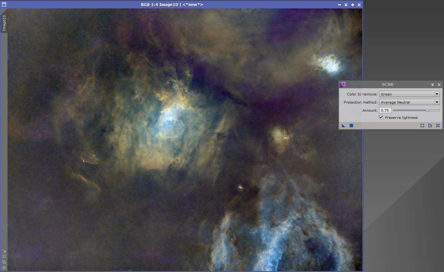
To remove the magenta is easy. As magenta is opposite to green on the colour wheel, by inverting the image and applying SCNR, the magenta background is removed. To invert the image, select Invert from Processes/All Processes.
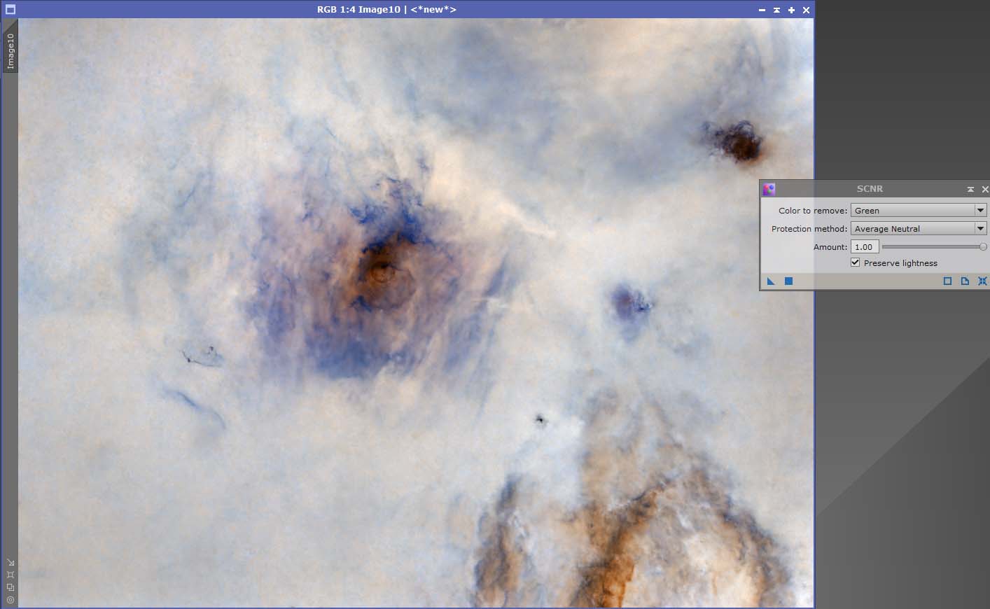
Apply the SCNR to the inverted image. Then invert the image back, you will have removed the magenta background.
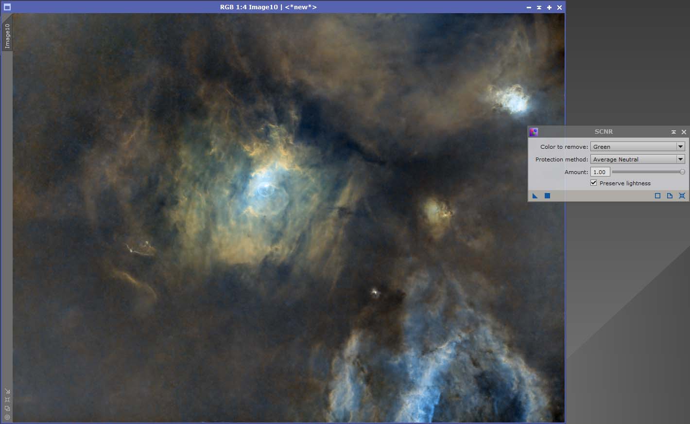
The same process can be applied to your stars to remove green or magenta.
Everything from this point on, is subject to taste. The brightness, color saturation can all be adjusted in the Curves process. Open up curves, open the real time preview and adjust until you are happy. Apply adjustments in small increments by using the blue square on the curves process, reset curves, then apply another adjustment, until you are happy.
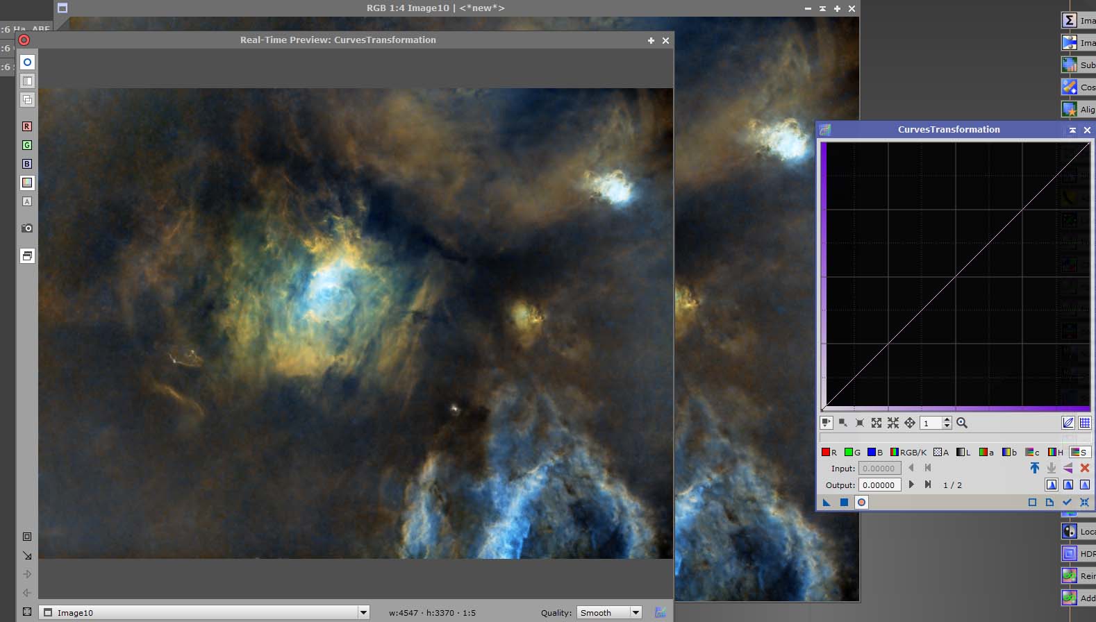
To reintegrate stars, first we need to rename the 2 image files. Rename the stars image to stars, all lowercase. Rename the main image file to starless. To rename your images, right click on the tab, select identifier.
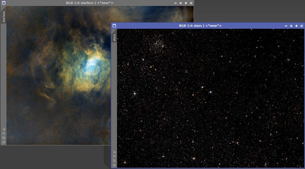
Next we need to open PixelMath in Processes/All Processes. Copy the settings exactly as in the image. Here is the code to copy and paste into the RGB/K tab.
combine(starless, stars, op_screen())
![]()
Press the blue square on the process, you will have a new image with the stars reintegrated into your starless image.
![]()
The final image should be saved in the .xisf format. It can also be saved as a tiff, to make other adjustments in Photoshop. Ensure you save the file as a 16 bit.
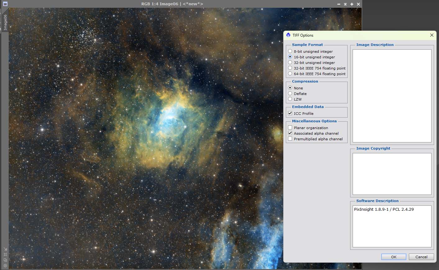
This concludes this very basic introduction to Pixinsight. I have only scratched the surface of the capabilities of this fantastic software. I will upload more advanced techniques in the future, which will improve your images even more.
